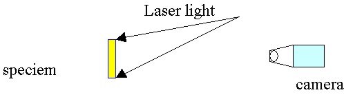
DETERMINATION OF MATERIAL CONSTANTS BY PRECISE LASER DEFORMATION MEASUREMENTDr Yu-Min CHANG, Taipei, ChinaKey words: Laser Deformation Measurement, Material Elastic Constants, Young’s Modulus, Poisson’s Ratio. AbstractThe properties of material can be understood by obtaining its material constants. Due to the complication of measuring environments, the traditional measurement technique of material constants is difficult, especially in high-temperature measuring environment. This study offers a precise technique of laser deformation measurement to determine the various material constants under the condition of high-temperature. It is based on Laser Speckle Photography, which is used to measure the displacement of three different kinds of metal materials in variable temperature. In this way, we can overcome the harsh condition of high-temperature measuring environment. The displacement data gained is then transformed into the strain data. The acting forces inflicted on the specimen is measured by the counter weights. Afterward, the inflicted strain force, along with the section area of the specimen, is once again transformed into strain data. Finally, the elastic constants of the isotropic materials are immediately obtained. The initial experimental results are satisfactory in the civil engineering. If the sources of error are rightly corrected, the precision of the material constants will be greatly enhanced. Compared with the traditional contacted method, the technique has the advantages of easily-setup, non-destruction, the lower requirement of base isolation and high-precision. Especially, the technique not only can be wholly monitored but also achieves a breakthrough concerning the measuring difficulties of high-temperature environment. 1. IntroductionThe highly coherent property of laser has been applied to surface profile measurement. Every point on the laser-illuminated surface can be treated as a new light source and emit second light wave. The phase and amplitude difference of emitted waves represent the surface profile [1]. The interference detected speckle pattern was used to measure the surface shifting quantity [2]. The same technique was also used in stress concentration, flexure of plate and impact stress analysis [3, 4]. By computer image analysis, Young’s fringes separation can be calculated from speckle pattern point-wise filtering[5]. The displacement of structural elements can also be measured by laser measurement techniques[6]. In high temperature environments, in addition to material intrinsic intensity, thermal stress and mechanical stress reaction is also considerable. However, it is difficult to use traditional contact measurement method such as strain gauge. By simple optical setup, it is convenient to measure the deformation non-contactively, non-damageably and sensitively. 2. TheoryIn this paper, laser speckle photography is used here to determine elastic constants of material under specific thermal loading in high temperature. The optical setup for recording the specklegram is shown in Figure 1. Subjective speckle is recorded by this setup. The image was captured by two times exposure method.
Fig. 1 Optical setup for recording the specklegram. A small region of the developed and fixed speckle film was illuminated by narrow laser beam. The Young’s fringes vertical with shifting direction were observed on the screen. Speckle structure in the second time illuminated region is assumed to be same with the structure in the first time. The difference between the speckles of two times was shifting by a uniform displacement d. Those one-to-one corresponding speckles have same separation and orientation. After being illuminated by laser, the same double-holes diffraction occurred and regular Young’s fringes were shown on the screen. The relation between fringe separation s and double-hole separation d was
Where L is the distance between speckle pattern and screen, λ is the wavelength. The opening displacement of crack-tip of three-point bending specimen was measured by point-wise filtering. Because the displacement is the result of shifting, rotation and deformation, it is necessary to fix the sample carefully to prevent movement under force acting. Two spots (double spots) on the same film speared by a displacement p, which is proportional to the speckle displacement d.
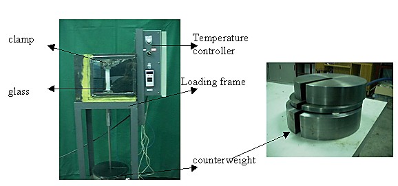
Where M is the magnification of the optical system. By analyzing the separation and orientation of those double spots, the shifting quantity and deformation can be derived. 3. Experiment and results304 stainless steel, 6001 aluminum and bronze were measured in the experiment. The white samples with size 200*60*3mm were fixed on loading frame with temperature control and loaded by varying weight as shown in Fig. 2.
Fig. 2 Schematic diagram of loading frame with temperature control The central region image was captured and
magnification is equal to be 1 by setting the object distance to be
the image distance. The image was captured after the temperature
remained one minute under the heater control. The exposed time
depended on the light power and power meter characteristics. The
strain of the sample occurred by varying the loaded weight. After
double exposing, the film was developed by chemical processing.
Finally, a proper coordinate x-y was chose on film to analysis the
deformation. Measuring and calculation the interference Young’s
fringes, then the material constants including determined the strain
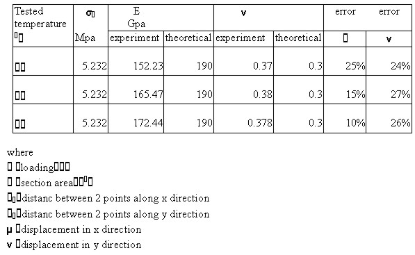
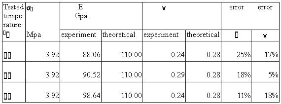
of these samples elastic modulus E and Poisson’s ratio Table 1. Experimental results for 304 stainless steel.
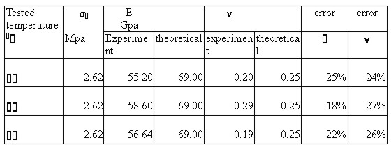
Table 2. Experimental results for 6001 aluminum
Table 3. Experimental results for bronze.
From the experiment data in table 1-3, the error of elastic modulus is 10 to 25 and the error of Poisson’s ratio is 5 to 27 . All the errors are within the civic engineering requirement 30 . The main sources of errors come from the artificial optical parallax of the measurement of Young’s fringes, the thermostatic setup of the temperature-controlled box, the instrumental error of the specimen fix-up, and the motion error of the rigid body of counter weights. In order to get more precise results, prevent sample-rotation prevention and well temperature control are necessary in experiment. 4. Conclusion and ProspectThis study offers a precise technique of laser deformation measurement to determine the various material constants under the condition of high-temperature. The initial experimental results are satisfactory, as indicated in tables 1-3. If the sources of error are rightly corrected, the precision of the material constants will be greatly enhanced. Compared with the traditional contacted method, the technique has the advantages of easily-setup, non-destruction, the lower requirement of vibration isolation, high-precision, and can be wholly monitored. The technique especially achieves a breakthrough concerning the measuring difficulties of high-temperature environment. As far as the future prospect is concerned, we hope that the laser measurement techniques can be applied to the study of the destruction by heat impact resulted from the impact stress of heat inflicted on the ceramic material. The ceramics, a kind of structural material widely used in high-temperature, often suffer from the destruction by heating stress generated by the dramatic changes of temperature inside materials. Also, it’s our hope that the combination of the photographic system and the image processing technique can eventually take the place of the traditional skill of negative exposure. By this, we hope to probe into the general impact generated by the heated stress and high temperature on the various testing materials. References[1] C. M. Vest, 1976, "Holographic Interferometry" John Wiley & Sons, New York, pp.396-428。 [2]. Leedertz, J.A., 1970, "Interferometric Displacement Measurement on Scattering Surface Ultilizing Speckle effect," J. Phys. E, Sci. Instr., vol.3, pp.214-228. [3] W. T. Evans and A. Luxmoore, 1974, "Measurement of In-Plane Displacement around Crack Tip by a Laser Speckle Method", Engineering Fracture Mechanics, vol.6, pp. 735-743. [4] F. P. Chiang, J. Adachi, R. Anastasi and J. Beatty, 1982, " Subjective Laser Speckle Method and its Applications to Solid Mechanics Problem", Optical Engineering, vol.21, no.5, pp. 379-390. [5] Hugo.D, Navone, 1989, "Evaluation of an Automatic Fringe Measurement Method for Analysis of Speckle Photography Data", Optical Engineering, vol. 28, no.9, pp. 1009-1013. [6] Rolando Gonzalez-Pena et al., 2000, "Displacement Measurements in Structural elements by Optical Techniques", Optics and Lasers in Engineering, vol.34, pp. 75-84. CONTACTYu-Min Chang 20 April 2001 This page is maintained by the FIG Office. Last revised on 15-03-16. |