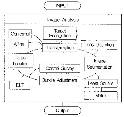
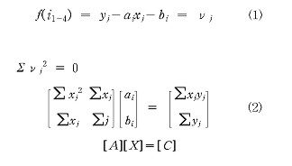
THE COMPONENT DEVELOPMENT OF DIGITAL CLOSE RANGE PHOTOGRAMMETRY FOR THE CONSTRUCTION STRUCTURE DISPLACEMENT ANALYSISSangho BAE, KoreaKey words: DCRP, Segmentation, Ellipse Fitting, Displacement. AbstractIn this study, this researcher designed the routine of image analysis with object concept, so as to increase the efficiency of displacement interpretation of structure by digital image analysis. For the hierarchical connection performance of analysis routine, this researcher formed the constant attribute of objectification of photogrammetry process by constituting the classes such as target location, transformation of coordinates of scan image, bundle adjustment, and direct linear transformation (DLT). And, this researcher performed the efficient location of sub-pixel coordinates by manufacturing the routine of coordinates location of image including target recognition, grouping, image segmentation and location etc. and the module of additional functions such as the establishment of pixel size and the indication function of recognized target. For the development of component of digital photogrammetry that the location of sub-pixel of high accuracy is possible, this researcher extracted the image segmentation (T-3) method which uses the average and standard error of greylevel values in search area, and ellipse fitting (ELI) method by edge detection and thinning by executing error analysis by the methods of coordinates location of sub-pixel, and could know that the accuracy of location is improved in accordance with the increase of threshold value. And, by developing the component to be based on the establishment of hierarchical diagram of classes through designing each subject of process of image analysis with the class of objectification concept, more efficient displacement interpretation of structure was possible. 1. OOP METHODExisting application program was the program of procedure type. Then, user could not help performing only in accordance with fixed routine regardless of the processing course or flow of program. But, the development of program to be able to reinforce the interface with user came to be possible, as the establishment of system of windows environment of GUI came to be possible. Object oriented program solves the problem through the transmission of message mutually among objects by prescribing the issues to require the processing of data of characteristic of engineering as objects and generating event. Object is performed by message transmission through method as the conglomerate to include data and operation, and the class for expressing object has the general behavioral style and the state variable within. Like this, Object oriented programming technique is the programming of compromise type which uses the core element to be object and has the merit to be able to take the reuse, expansion and conservation of object efficiently from the viewpoint of characteristic of software.In this study, this researcher used the object oriented programming technique which introduces the object oriented design concept in the software engineering. Fig. 1 is what showed the hierarchical diagram of class of windows application program to move on the basis of message. Then, user gets to complete program by defining the reaction on event. (Bae,1999) Fig. 1 Hierarchical Diagram of Class of Digital Photogrammetry
|
 |
 |
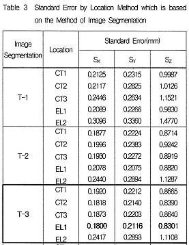
2.2.1 Standard Error to be based on the Method of Image Segmentation
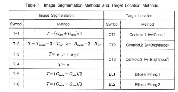
One of important courses of image processing which have influence on the location accuracy of target is the establishment of threshold value by image segmentation. As, the size and form of target change by threshold value, the method of image segmentation for dichotomizing the background image that greylevel value is close to 0 and the target image that it is close to 255 is the course of image processing to have to consider necessarily for the improvement of location accuracy of target.
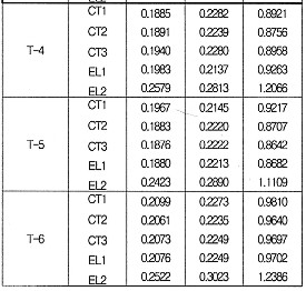
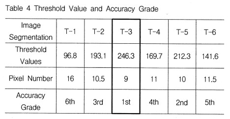
As the result that this researcher executed error analysis by applying the method of image segmentation and the location method like table 1 to the image of DCS200 camera and the image of same time zone of scan 15, this researcher could extract the average standard error and 3 dimensional position error of XYZ axes like table 3. From this, this researcher could know that T-3 method of image segmentation which uses the average and standard error greylevel information in search area shows relatively better accuracy to show the relation between threshold value and accuracy which are based on the method of image segmentation on the basis of result of error analysis of table 3 is as is in table 4. This showed the tendency that the number of target to include decreases and the accuracy is improved as threshold value is big and that the number of target to include increases and the accuracy decreases relatively as threshold value is small as what showed the relation among method of image segmentation, threshold value, target size, and accuracy. From this, this researcher could know that T-3 method of image segmentation which uses the average and standard error of greylevel value in search area shows high efficiency about the pixel information of target image.
2.2.2 Standard Error to be based on the Location Method
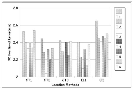
This researcher calculated the coordinates result of target and the error analysis by applying the technique of centroid location which enables the sub-pixel location of image coordinates and the ellipse fitting(EL) method to be based on edge detection through subdividing the pixel to be the physical location unit of system. Fig. 6 is what illustrated 3 dimensional position error by the method of image segmentation which is based on the location method. This researcher could see that fig. 6 shows minute size but better accuracy in comparison with the location method that EL(I) method is different as the result that this researcher executed the error analysis to be based on location method by using the image of same time period which was acquired with 2 SV-D100
Fig. 6 3-dimensional Position Error by the Method of Image Segmentation which is based on the Location Method camcoders. And, out of centroid location methods, CT2 method which used greylevel value as weight showed more improved accuracy. The result interpreted by applying location EL(II) method showed the accuracy distribution which is low relatively in comparison with the accuracy interpreted by applying other location algorithm, and it is considered that this became issue in the algorithm arrangement of mathematical model formula.
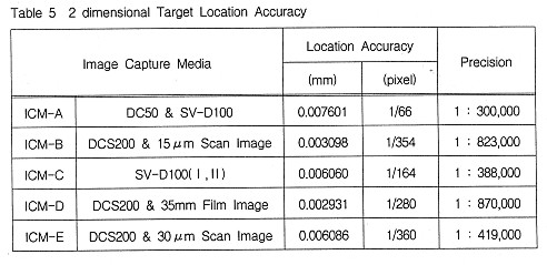
2.2.3 2 dimensional Target Location Accuracy
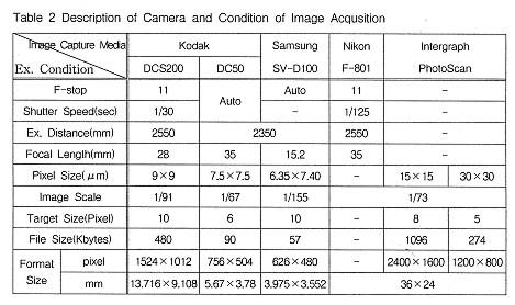
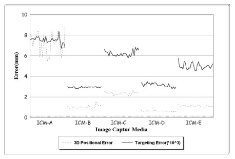
This researcher analyzed the location accuracy of sub-pixel of target by the image capture media by applying T-3 method of image segmentation and EL1 method of location to the image of same time zone. Table 5 is the result which extracted 2 dimensional location accuracy of target by analyzing the solid model to be based on the image capture media afterwards. In case of interpreting the image of same time zone of DCS200 and scan 15?, this researcher could obtain 2 dimensional target location accuracy of 3? or so and the pixel accuracy of 1/354. And, this researcher could obtain the precision of 1:800,000 or so at 2.6m or so of photography distance. Fig. 7 is what illustrated the relation between 2 dimensional target location accuracy and 3 dimensional position error which were interpreted by the method of image segmentation and the location method by the image capture media. Then, this researcher could know that 3 dimensional position error which is based on interpretation method becomes larger as irregular aspect as the location error of target becomes larger. Therefore, we can see that we should improve the location accuracy of sub-pixel of target and that the establishment of location algorithm of sub-pixel of high accuracy and the development of processing software are essential with the development of hardware that the image acquisition of high resolution is possible.
Fig. 7 2-dimensional Target Location Accuracy and 3 dimensional Position Error
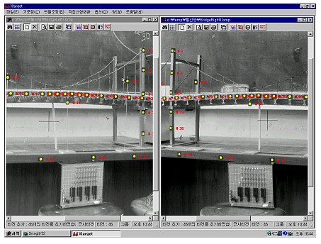
2.3 Location of Displacement
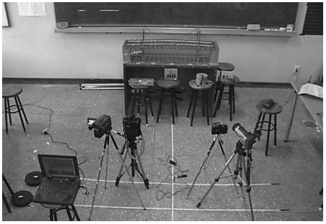
So as to measure the displacement of observation model which is based on load change, this researcher interpreted 22 image points attached to beam by loading total 9.6kg by 1.6kg by stages and applying T-3 method of image segmentation and EL1 method of location at initial state. In case of ICM-A, this researcher acquired the image of same time zone which is based on the load change of 7 stages by using DC50 and SV-D100, and it showed the standard error of Y axis (hanging direction) of 1.8918 or so. This is considered as the result induced from the systematic instability and low resolution of DC50 camera which showed serious lens distortion. The case of ICM-C showed the standard error of Y axis of 0.9641? as the result analyzed by capturing the image of same time zone which uses timer from the continuous frame acquired by using 2 SV-D100. As this may reduce the required time to be based on the acquisition and processing of on-line data in comparison with steel video camera, it is expected that establishing the hardware such as the image capture board of high resolution which can capture the increase of frame number per second and the momentary frame may increase the application for the location of displacement and momentary conduct of structure.
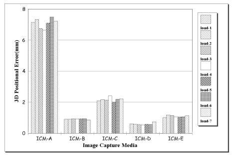
Fig. 8 3 dimensional Position Error by Load which is based on the Image Capture Media axis of 0.2 or so.
The case of ICM-D analyzed by using the image of DCS200 and the image of 35 film showed relatively most improved standard error of vertical direction of 0.1816 , and the case of ICM-B and ICM-E interpreted by scanning film image showed the standard error of the direction of Y.
Fig. 8 is the result which illustrated 3 dimensional position error by load which is based on the image capture media. In case of analyzing the image of same time zone of scan of DCS200 and 15 film, the hanging quantity of 5.648? was generated at the time of loading 1.6kg, and the hanging quantity of 8.433? was generated at the time of loading 9.6kg. Thus, it could be seen that 70% or so of whole hanging quantity is generated at the time of initial loading. At this time, the standard error of vertical direction is 0.1819. Fig. 9 is the result which illustrated the displacement quantity of vertical direction which is based on load in initial state as relative coordinates result.
Like this, as I could create the base of module of image analysis that the addition and renewal of diverse camera in digital image, it is considered that many applications in diverse fields will be possible.analysis modules are easy in this study, it is considered that management will be possible by grafting various modules for performing the displacement interpretation of structure more efficiently through expanding the class of objectification concept of digital photogrammetry. And, as the interface and processing of on-line data are possible from CCD camera or digital.
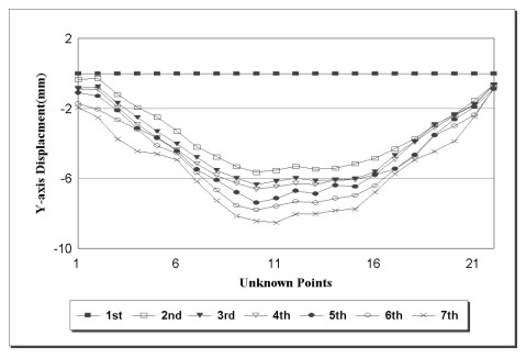
Fig. 9 Vertical Displacement of Imitation Bridge which is based on Load
It is expected that the possibility to put digital photogrammetry to practical use will be very great as the location technique of version for the interpretation of displacement of large-size structure in civil engineering and diverse industry fields, if much study on the development of digital camera and analysis system is performed
3. CONCLUSION
- For the analysis of digital image, this researcher developed
object oriented digital photogrammetry component by designing and
establishing the hierarchical diagram about the class of user and
the processing routine of data with objectification concept.
- For the hierarchical connection performance of analysis routine,
this researcher created the objectification structure of
photogrammetry process by constituting the classes such as target
location, coordinates transformation of scan image, bundle
adjustment, and DLT.
- This researcher could uplift the reliability of coordinates
location of target and could establish reject limit for promoting
the efficiency of target, as this researcher established the
system of image coordinates by deciding the outer block part of
scan image through the method of edge detection.
- This researcher could see that the method of image segmentation
(T-4) which uses the average and average error of greylevel
information in search area and the ellipse fitting method(EL1) to
be based on edge detection are ideal for the location of sub-pixel
of target.
- This researcher could perform the displacement location of
imitation bridge more efficiently by developing the component to
be able to expand the class of diverse subjects through designing
each subject of digital photogrammetry process with the class of
objectification concept.
- It is expected that the application will be expanded to various industrial fields as well as construction field, if we seek the on-line of system that the location of real structure of real-time is possible with the continuous study for the improvement of accuracy of digital photogrammetry, in the future.
BIBLIOGRAPHY
- Amirn Saeed Homainejad(1996). The Problems of Real Time Photogrammetry. The Univ. of New south Wales.
- Bae, Sang-Ho, Kang, Jook-Mook, Song, Seung-Ho (1999). The Construction of Digital Photogrammetry System Using Windows Environment. The Journal of Korean Society Civil Engineering, Vol.19, ?-2; 325~334.
- Clive S. Fraser(1991). A resume of some industrial applications of photogrammetry. ISPRS Journal of Photogrammetry and Remote Sensing.
- C.W. Urquhart, J.P. Siebert(1993). Towards Real-Time Dynamic Close Range Photogrammetry. SPIE Videometric, Vol. 2067: 240~251.
- D. Cosandier and M.A. Chapman(1992). High precision target location for industrial metrology. SPIE,Vol.1820: 111-121, Videometrics.
- Firooz A.Sadjadi(1997). Automatic target Recognition . SPIE.
- Han, Seung-Hee(1995). 3D Modeling of Automobile part Based on CCD camera. SPIE, Videometric?, Vol. 2598: 149~160.
- J.C. Trinder,J. Jansa and Y. Huang(1995). An assessment of the precision and accuracy of methods of digital target location. ISPRS:12-20.
- M.R. Shortis, T.A. Clarke, and S. Robson(1995). Practical Testing of the Precision and Accuracy of Target Image Centering Algorithms. SPIE Videometrics, Vol. 2598: 65-76.
CONTACT
Sangho Bae
Full Time Lecturer, Civil Eng.
Daelim College
526-7 Bisan Dong
Dongan Gu
Anyang
KOREA
Tel. + 82 31 467 4912
Fax + 82 31 467 4910
E-mail: shbae@daelim.ac.kr
13 April 2001
This page is maintained by the FIG Office. Last revised on 15-03-16.