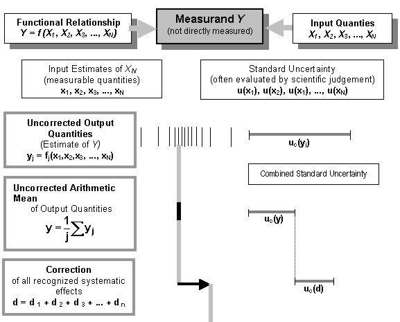
A NEW CONCEPT FOR STATING ACCURACY IN STANDARDS - EXEMPLIFIED BY ISO / DIS 17123-6 ROTATING LASERSProf. Hans HEISTER, GermanyKey words: SUMMARYWhen reporting results of measurements, especially test and calibration quantities, it is necessary to state the accuracy. In the last decade detailed instructions and recommendations were published by different international groups involved in metrological tasks. The final objective was to develop a guidance document on the expression of uncertainty in measurement. The paper will discuss this new concept of uncertainty especially in connection with testing and calibration procedures of surveying instruments. A numerical example in connection with the ISO Standard on Rotating Lasers is presented to demonstrate the scheme of computation. ZUSAMMENFASSUNGBei der Überprüfung und Kalibrierung von Vermessungsinstrumenten ist es üblich, neben dem Ergebnis auch seine Genauigkeit anzugeben. Speziell bei hoch genauen Anforderungen ist eine zuverlässige und zutreffende Quantifizierung des Genauigkeitsmaßes gefordert. Benutzte der Geodät bislang vorrangig die Standardabweichung als Genauigkeitsmaß seiner Messungen, so wird zunehmend besonders in den meßtechnischen Nachbardisziplinen der Begriff Meßunsicherheit benutzt. Das international eingeführte Konzept zur Ermittlung von Meßunsicherheiten wird im nachfolgenden Beitrag speziell im Zusammenhang mit der Überprüfung geodätischer Instrumente und den hiermit verbundenen Normen vorgestellt. Am Beispiel der ISO-Norm Rotationslaser wird der Berechnungsweg zur Bestimmung des Genauigkeitsmaßes Meßunsicherheit näher erläutert. 1. INTRODUCTIONWhen reporting the results of instrumental investigations, it is obligatory that some quantitative indication of the quality of these tests or checks is given so that those who want to use it can assess its reliability. Without such an indication, the results cannot be compared, neither among themselves nor with reference values, given in the specifications or standards. Today predominantly the quantity "standard deviation" is used to indicate the accuracy of our instruments. As this value considers more the stochastic, random errors it becomes more and more necessary to regard as well the systematic effects. The reason for this is that due to the clear improvement of the instruments the random component becomes smaller in comparison with the systematic component. It is therefore necessary that we use readily implemented, easily understood and generally accepted procedures for stating the quality of geodetic and surveying instruments. For this reason the paper will discuss the concept of uncertainty especially in connection with the standards of the series ISO 17123 "Optics and optical instruments - Field procedures for testing geodetic and surveying instruments". Part 6 of these standards - Rotating Lasers - will be used as example to demonstrate the qualitative and quantitative difference between the old and new accuracy concept. 2. THE UNCERTAINTY OF MEASUREMENTThe definition and concept of uncertainty as a quantitative attribute to the final result of measurement was developed mainly in the last two decades, even though the error analysis has already long been a part of all measurement sciences. The highest authority, the Comité International des Poids et Mesures (CIPM), requested in 1977 the Bureau International des Poids et Mesures (BIPM) – after recognizing the lack of international consensus on expressing measurement uncertainty – to treat the problem in collaboration with the national standards laboratories and to make recommendations. After several stages the CIPM referred the task of developing a detailed guide to the International Organization of Standardization (ISO). Under responsibility of ISO Technical Advisory Group on Metrology (TAG 4) and in conjunction with six worldwide metrology organizations a guidance document on the expression of measurement uncertainty was compiled with the objective to provide rules for use within standardization, calibration, laboratory, accreditation and metrology services. The Guide to the Expression of Uncertainty in Measurement (GUM) was first published as ISO document in 1995. As the Guide provides more general rules for evaluating and expressing uncertainty in measurement all relevant terms are here discussed in conjunction with the known geodetic measuring procedures (s. fig. 1 ): In geodetic / surveying applications we are normally dealing with the measurands (Y) length and angle. But often they are not primarily measured. Such as during distance measurement we measure for example time and phaseshift or controlling frequency and temperature. That means we have a lot of input quantities Xi on which the measurand depends. From a theoretically established functional model we will obtain the desired measurand
But the specific measuring process will provide only the input estimates of XN , the measurable quantities x1 , x2 ,x3 , . . . , xN . Each input estimate xi is associated with the standard uncertainty u(xi) . This standard uncertainty is in principle equivalent with the experimental standard deviation s(xi) of its input estimate xi . But in many cases hereof little or no information is provided. Thus the associated estimated standard uncertainty is based on experiences or general knowledge of the behavior and properties of the relevant sensor. Using all input quantities the result of one measurement, the uncorrected output quantity, is given by
where j indicates the number of determinations for the output estimate y. Its uncertainty is obtained by appropriately combining all u(xi) and is denoted uc(y) , the combined standard uncertainty of the estimate y, the result of measurement. In general this value is displayed, in our example as "measured distance", at the instrument. Unfortunately the process of evaluating y is mostly not known. It is therefore often difficult to determine the combined uncertainty with the desired reliability.
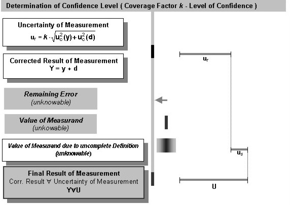
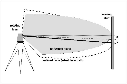
Figure 1: Result of a measurement and its uncertainty If we recognize in the measurement procedure systematic effects and we know the arithmetic rule to calculate its value, we have to apply corrections for compensating these effects. But an important requirement is: Each correction dn has to be significant in size relative to the achieved accuracy of the measurement. Often, measuring instruments are adjusted or calibrated already by the manufacturer or even by the user to eliminate systematic effects before displaying. That means: In a sense the measurement y is already the corrected result, but the uncertainties associated with the corrections are frequently neglected, mostly however they are unknown. A typical example in distance measurement is the additive constant and the short periodic error: In modern electronic tacheometers both components are already considered in the displayed measurement, but the uncertainties are not regarded. This simple example likes to clarify that the transition of the uncorrected output to the corrected result of measurement in practice is fluently. To meet the needs of industrial and commercial applications it is required to provide an interval of confidence about the result of measurement. For this a coverage factor k is defined, with which the combined standard uncertainty is multiplied: the result is the expanded uncertainty ur. The choice of the coverage factor k is based on the level of confidence. The intended purpose is to create an interval about the result, which may encompass a large fraction of the distribution that could reasonably be attributed to the measurand. In the practice, the choice of k = 2 results an interval that corresponds to a probability of approximately 95%. Due to the unknown remaining errors and approximate functional relationships we will have always and in each measuring procedure a remaining difference between the value of the measurand and the corrected result of measurement Y. For this reason it is necessary to introduce an additional uncertainty component us. It depends on the experience of the observer to estimate a representative value for this component. Finally we can state the uncertainty of measurement U of the result by summarizing the two uncertainty components, either squared or linear. 3. THE ISO STANDARD FOR ROTATING LASERSAs discussed in Zeiske (2001) the SC 6 of ISO / TC 172 has treated several standards on field procedures for testing geodetic and surveying instruments. ISO 17123 - Part 6 of these standards – Rotating Lasers – describes two testing procedures, the simplified and full test procedure, both with the objective to determine a representative quantity for the experimental standard deviation of a single measured height difference (instrument – leveling staff). Additionally in the more comprehensive full procedure two systematic errors can be separated from observations: the deviation a, which is a measure for the inclination of the rotating laser plane and the deviation b, which is effected by a non-orthogonality between laser path and standing(rotating) axis (s. fig. 2). The ISO DIS 17123 –Part 6 - still under discussion – describes in detail the whole test procedure and the analysis of the observation series. The result is the experimental standard deviation s ISO-ROLAS as a measure of precision in use for the investigated rotating laser level, referenced to a sighting distance of 40 m. Further more we will obtain the two systematic deviations a and b. It is not common practice to correct the observation during practical field operation. For interpretation of all results – in particular the additional parameters a and b - several statistical tests will employed. Thus the customer obtains objective criteria to accept the accuracy specifications of the tested instrument.
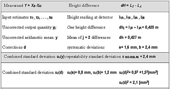
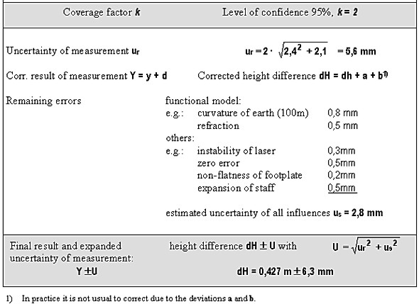
Fig. 2: Systematic deviations of a rotating laser level 4. STATING THE MEASUREMENT UNCERTAINTY OF ROTATING LASERSAlthough in surveying in many cases the strict use of measurement uncertainties is not always required, the expression accuracy should treated much more comprehensive. Especially in metrological oriented applications like precise measurements for testing and calibrating of geodetic instruments (Heister, 1999). The following example will demonstrate the advantage of the proposed method for stating accuracy. The standard ISO DIS 17123 – Part 6 provides user friendly tests with the objective to determine precision in use. The result is the repeatability standard deviation for the specified measuring procedure. But in practice the additional parameters a and b, both are standing for systematic errors in the measuring process, influence considerably the accuracy. The suited concept to regard all these systematic effects in your accuracy budget is the uncertainty in measurement. With the terminology of chapter 2 one will come to the analogy and calculation scheme (fictive numerical values) of the uncertainty of measurement, compiled in table 1. This example tries to demonstrate what the expression uncertainty of measurement embodies. The repeatability standard deviations, as they are determined in the standard ISO 17123 is only one component in characterizing the accuracy of a surveying instrument. The common user or even the expert, who is not as specialized in solving metrological tasks, might incorrectly interpret this accuracy statement. Although the framework in chapter 2 or the GUM provides instructions to assess uncertainty, it cannot substitute critical thinking and professional skill. Especially in defining and modeling all the systematic effects, which can influence the uncertainty, a detailed knowledge of the principles and methods of measurement are essential requirements. The question of summarizing the uncertainties or the correct treatment of correlations was hardly touched in this contribution. The more interested reader therefore is referred to the Guide to the Expression of Uncertainty in Measurement (ISO 1995) or to Schmidt (1994), (1997).
Table 1: Scheme for the calculation of the uncertainty of measurement of rotating lasers (numerical values are fictive) 5. CONCLUSIONSIt is obvious that there are two major reasons for reconsidering the approach of stating the measurement uncertainty as a suited quantitative measure of accuracy in testing and calibrating geodetic instruments:
All these operations require defined accuracy statements, which are nationally and internationally recognized and for everybody comprehensible. With the uncertainty of measurement both a term was created and recommendations for quantifying, which will met all metrological requests. There is no doubt, it is not necessary to give an explicit report on uncertainty for routine surveying tasks. However numerous measurements are performed everyday with instruments subjected to periodic checks or calibrations. At least the normative documents of these checks should include detailed particulars concerning the uncertainty of measurement. As higher one moves up the measurement hierarchy as more details are required on how the measurement result and its uncertainty is obtained. At any level of this hierarchy, including routine or engineering work in industry, industrial or academic research, primary standards and calibration laboratories and even the quality control of the manufacturers, all of the necessary information must be made available for everybody in form of published certificates or test reports, instruction manuals or national or international standards. Only the most possible transparency of this chain may guarantee best measurement results and most reliable accuracy statements. LITERATUREHEISTER, H. (1999): Checking, Testing and Calibrating of Geodetic Instruments. In Lilje,M.(Ed.): Geodesy and Surveying in the Future - The Importance of Height. Proceedings, Gävle 1999, 239 - 247 RÜEGER, J.M., BRUNNER F.K. (1999): On the System Calibraton and Type Testing of Digital Levels. Zeitschrift für Vermessungswesen (ZfV), im Druck SCHMIDT, H. (1994): Meßunsicherheit und Vermessungstoleranz bei Ingenieurvermessungen. Veröffentlichungen des Geodätischen Instituts der RWTH Aachen, Nr. 51 SCHMIDT, H. (1997): Was ist Genauigkeit? Zum Einfluß systematischer Abweichungen auf Meß- und Ausgleichungsergebnisse. Vermessungswesen und Raumordnung (VR) 59 ZEISKE, K.(2001): Current status of the ISO Standardization of Accuracy Determination - Procedures of Surveying Instruments. Proceedings, FIG WW Seoul STANDARDS AND TECHNICAL MONOGRAPHSISO/DIS 12123 - Part 1, ..., 6 (2000): Optics and optical instruments - Geodetic and surveying instruments -Field procedures for determining accuracy. FIG-PUBLICATION (1994): Recommended Procedures for Routine-Checks of Electro-Optical Distance Meters (EDM). FIG Technical Monograph No. 9., Canberra, Australia ISO (1995): Guide to the Expression of Uncertainty in Measurement. International Organization for Standardization, Genève CONTACTProf. Dr.-Ing.habil. Hans Heister 30 April 2001 This page is maintained by the FIG Office. Last revised on 15-03-16. |